1. Introduction of fuel cell system

For the five main fuel cells with current market prospects: proton exchange membrane fuel cells, solid oxide fuel cells, alkaline fuel cells, molten carbonate fuel cells and phosphoric acid fuel cells. They all have their stable fuel cell systems, and they all need to be integrated into a fuel cell system for specific market application requirements, which is also the feature of these fuel cells. As a result, fuel cell systems (alkaline fuel cell AFC, polymer electrolyte fuel cell PEFC) with fast startup speed, good thermal and electrical cycle characteristics, and low operating temperature range can be used both in stationary applications and in the field of transportation. mobile application. In contrast, those fuel cell systems operating in higher temperature regions (MCFC, phosphoric acid fuel cell PAFC, SOFC) are not sufficient to cope with the rapid temperature rise, so the fuel cell system requires a longer period of time. The start-up time is also sensitive to the process of thermal cycling. Therefore, the batteries of this fuel cell system can only be used in stationary applications. However, we still want to mention the specificity of SOFC and its application expectations. Despite the thermal management difficulties of this type of high temperature fuel cell (typical operating temperature of 800 °C), the electrolyte is solid and can be used Carbon monoxide is used as a fuel, which makes it a favorable option for transportation applications.
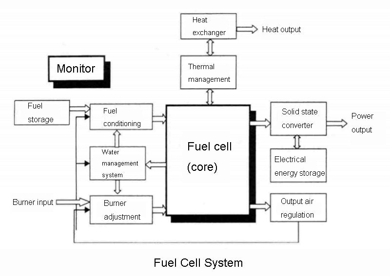
The fuel cell itself has excellent current dynamic response capability. However, those auxiliary functional units (regas supply circuit, air compressor, humidification system, cooling circuit, etc.) necessary for the operation of the fuel cell system do not necessarily have the same capability. Since these auxiliary fuel cell systems have different response times (from a few milliseconds to minutes), the performance of the fuel cell system is greatly degraded. So far, we have given the concept of a fuel cell system, which integrates and includes the fuel cell body, and various subsystems (accessories, devices) required to make it work properly. The following figure shows this fuel cell system. of the various components. We still need to emphasize again that the so-called fuel cell system generally refers to such a system as shown in the figure below. This definition is the same as the definition of fuel cell system given by the FCTESTNET (Fuel Cell Testing and Standardization Network) project, but is somewhat different from the definition given by IEC (International Electrotechnical Commission) or SAE (Society of Automotive Engineers), If necessary, we can find the difference by comparing. In any case, there is still a long way to go before competitive, high-performance, functionally segmented fuel cell systems enter the market.
2.Principle of fuel cell system

As can be seen from the above figure, for the fuel cell system, the first thing that bears the brunt is the manufacture and storage of fuel (especially when hydrogen is used as a battery fuel, although hydrogen compounds are the most common on earth, under natural conditions, almost no hydrogen exists). The fuel is then conditioned for pressure, temperature, flow, and humidity, and then charged into the fuel cell's anode plenum. The combustion agent must go through the same conditioning process before entering the cathode plenum. Moreover, in order to humidify the reaction gas entering the fuel cell, we can recover the water generated by the electrochemical reaction inside the fuel cell system and carried out by the exhaust gas in either of the two gas loops. Under certain conditions and certain operating modes, fuel cells can form a water self-sufficient system.
In addition, since the electrochemical reaction process of the fuel cell is exothermic, when the power of the battery is large (for example, higher than 1kW), it must be equipped with a dedicated cooling circuit using liquid coolant. The purpose of controlling the cooling circuit is to generally maintain the internal temperature of the battery within the nominal temperature rating range of the manufacturer. Of course, the cooling loop controller and the intake humidification controller of the fuel cell system must be linked together, because these two variables are closely related.
Finally, solid-state converters are often not necessarily required to convert fuel cell energy into electricity. Of course, fuel cells can also be used in combination with other power sources, such as supercapacitors or lithium-ion batteries, depending on the specific application requirements.
Of course, the control, especially the management of the various subsystems in the fuel cell system and the energy flow between them, requires a special monitoring device.
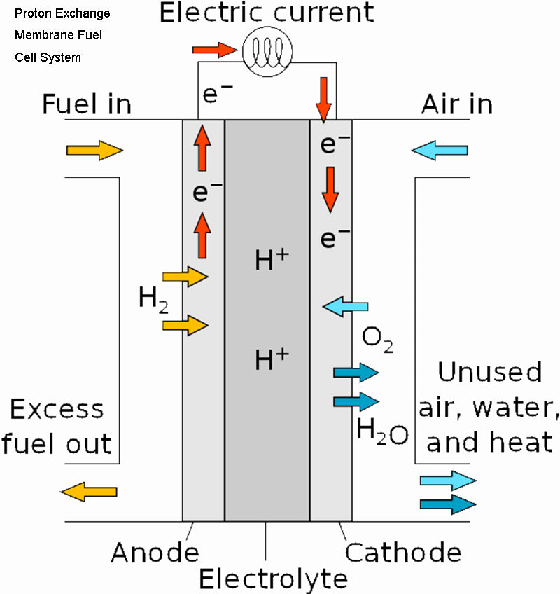
In order to be able to demonstrate the significant impact of these accessories on fuel cell performance, we use the most common proton exchange membrane fuel cell system (especially when we are interested in transportation applications) as an example to illustrate the different types of fuel cell systems in this category. Typical energy consumption of attachments.

First, we notice that the net power output from the fuel cell port is only 2/3 of the total power of the system. Secondly, among various auxiliary devices, the oxidant conditioning system (such application systems generally use air compressors) consume the most power. This is followed by the humidification system, solid state converter and cooling system. Note that here we assume that at the inlet of the system, the regassing exists directly in the form of compressed gas.
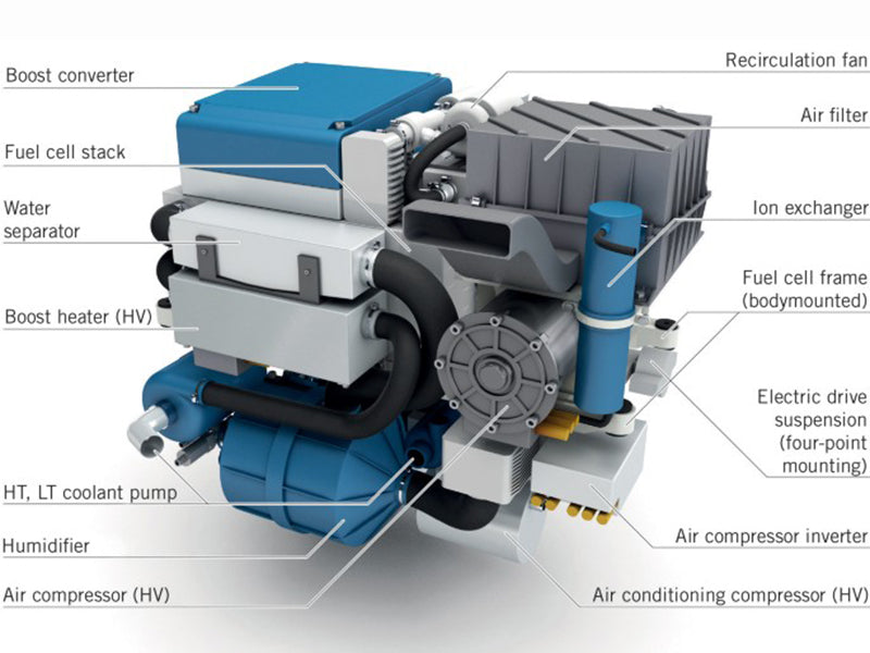
After the fuel cell system is defined, the main accessories of the fuel cell system have more details, including
1) Air (oxidant) supply system, usually a motor-driven compressor.
2) Gas humidification system.
3) Solid state converter for power output.
Each of them contributes to the operation of the fuel cell system.