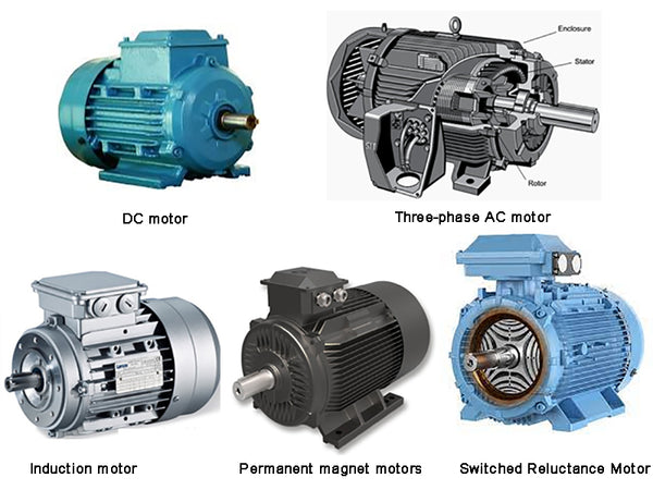
main content:
1. DC motor
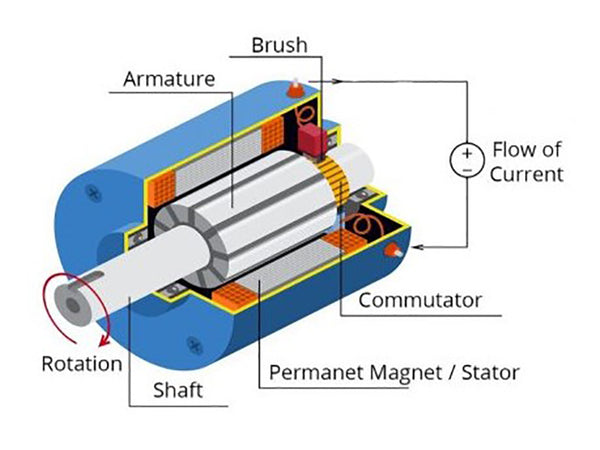
The DC motor is mainly composed of three parts: stator, rotor and brushes.
Among them, there are a set of windings on the rotor and the stator respectively, the windings in the rotor are called armature windings, and the windings in the stator are called field windings. Both the armature winding and the field winding are fed with DC current.
The armature winding generates the armature magnetomotive force through most of the current, while the excitation winding only generates the excitation magnetomotive force through a small excitation current. The magnitude of the magnetomotive force is determined according to the number of turns in the winding and the magnitude of the current. The two sets of magnetomotive forces interact to generate torque. The function of the commutator and the brush is to ensure that the two groups of magnetomotive forces are orthogonal, which is the basis for the motor to generate torque.
According to the number of input power and the connection form between the armature winding and the field winding, DC motors can be divided into separately excited DC machines and series DC machines.
① Separately excited DC motor
The input of the armature winding and the excitation winding of the separately excited DC motor are independently controlled DC power sources. Separately excited DC motors provide maximum flexibility for torque and speed control by independently controlling armature and field currents.
② Series DC motor
Another form of DC motor is the series-excited DC motor. Since the armature winding and the excitation winding are connected in series, the current flowing in the armature winding and the excitation winding is the same. Therefore, a coil with a larger wire diameter needs to be used to transmit the same magnetomotive force or ampere-turn. The biggest advantage of series-excited DC motors is that their starting torque is very high, which helps to improve rapid acceleration. But on the other hand, the series connection of the armature winding and the field winding also makes it lose the flexibility of control.
In general, the advantages of DC motors are as follows: easy controllability based on linearity; the ability to independently control torque and flux; mature manufacturing technology. However, DC motors also have corresponding disadvantages: the brushes are easy to wear, which leads to higher maintenance costs; the maximum speed is low; the electromagnetic interference (EMI) generated by the action of the commutator; the power quality is relatively low.
Separately excited DC motors used in pure electric vehicles or hybrid electric vehicles provide energy for the armature winding and the field winding through two independent DC/DC converters in the same energy source, as shown in Figure 1. The DC/DC converter converts the fixed input voltage in the energy source into a variable DC voltage that is input to the armature and excitation circuits. The rated power input by the converter to the armature winding is much larger than the rated power input to the excitation winding. . The input of the converter is controlled by the torque and speed required by the motor, and the output of the converter is the voltage acting on the armature circuit and the excitation circuit in the DC motor.
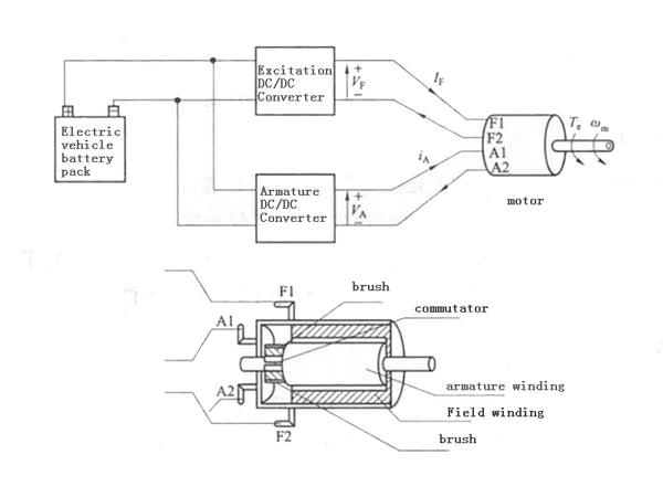
Figure 1 DC motor drive including power electronics and battery energy
The existence of independent armature voltage and field current controls in separately excited DC motors or motors provides additional performance optimization possibilities for meeting the torque-speed requirements of the motor. The drive performance indicators of the motor include efficiency, torque per unit current per ampere, torque ripple and response time, etc. The weight of each performance indicator depends on the actual application and design requirements, and is used in pure electric vehicles and hybrid electric vehicles. In the middle, its most important performance indicator is efficiency.
2. Three-phase AC motor
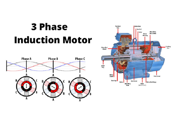
The main difference between an AC motor and a DC motor is that the armature circuit of an AC motor is located on the fixed part of the structure while the armature circuit of a DC motor is located on the rotor. The biggest advantage of having the armature circuit on the stator is that it can eliminate the commutator and brush structure in the flow motor. Therefore, the mechanical wear of the motor due to the commutator and the brush can be avoided, thereby increasing the reliability of the motor and prolonging its service life. The varying input current required by the AC motor can be provided by a DC power source through a DC/AC converter. AC motors can be divided into two types: single-phase AC motors and multi-phase AC motors. Single-phase AC motors are mainly used for low-power equipment, while high-power motors are usually three-phase structures. The rotor magnetomotive force (second MMF) used to generate torque in an AC motor (equivalent to the excitation magnetomotive force in a DC motor) is generated from the rotor circuit. According to the form of generating rotor magnetomotive force, AC motors can be divided into induction type and synchronous type. The stator winding structure of these two types of AC motors is similar.
①Synchronous motor
The rotor of a synchronous motor always rotates at synchronous speed. Rotor MMF is generated by a permanent magnet motor or DC current in the rotor coils. The latter form of synchronous machines are often used as large machines in electrical power generation systems. Permanent magnet motors are more suitable for pure electric vehicles and hybrid electric vehicles because they can provide higher power density and superior performance compared to motors that input direct current to the rotor.
②Asynchronous motor
In asynchronous motors, the rotor speed is close to but different from the synchronous speed. These motors are also called induction machines. In the common structure of this type of motor, the induction is only generated by the stator, and the voltage in the rotor circuit is caused by induction of a changing magnetic field with the stator. This induction in turn generates the electromagnetic force required for the rotor to rotate, so it is called an induction motor.
3. Induction motor
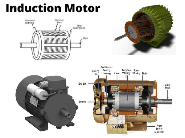
Induction motor is a kind of AC rotating motor, which has the advantages of simple structure, reliable operation, high efficiency, low price and durability. It is the most widely used motor in all walks of life and daily life. However, induction motors also have some shortcomings, such as poor starting and speed regulation performance, and the need to absorb inductive reactive power from the grid during operation.
Structurally, the induction motor mainly includes two parts: the stator and the rotor, and there is an air gap of 0.2~2mm between the stator and the rotor. Induction motors can be divided into two types: squirrel cage type and wound rotor type according to the different rotor sets.
Among them, the rotor end of the wound rotor induction motor is connected to the outside world through a slip ring, and the slip ring can control the motor speed. The rotor winding of the cage induction motor is composed of short-circuit windings, and the windings are composed of strip copper conductors and end rings in the slots, which are shaped like a squirrel cage. The structure of the rotor winding of the squirrel induction motor is shown in Figure 2. Due to the advantages of robust structure and low cost, cage-type induction motors are widely used in the industrial industry, and are also used in electric vehicles and hybrid vehicles.
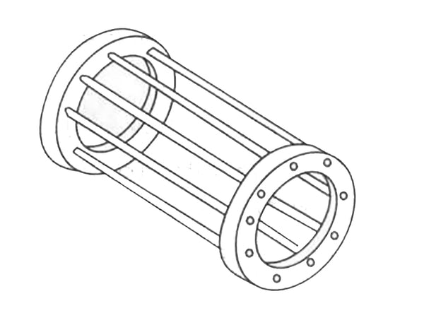
Figure 2 Structure of the rotor winding of a squirrel-cage induction motor
The rotor of the squirrel induction motor has two structures of cast aluminum rotor and copper row rotor. The two ends of the copper (aluminum) conductors in the rotor are connected by end rings to short the conductors to form a short circuit winding.
When there is a constant voltage input in the stator windings, a magnetic field is generated inside the motor, which rotates at a synchronous speed. According to Faraday's law, when the rotor speed is different from the synchronous speed (even the rotor speed is zero), the rotor conductor cuts the stator magnetic field, which produces a changing magnetic flux in the rotor's circuit, thereby generating an induced voltage. The principle is the same as that of the transformer, that is, the time-varying AC magnetic flux generated by the primary winding (stator) generates an induced voltage on the secondary winding (rotor) Since the rotor winding is short-circuited in the induction motor, the induced voltage generates current in the rotor circuit. An induction motor can be thought of as a transformer with a secondary or rotor winding shorted. Since the stator generates a sinusoidally varying magnetic field, the rotor generates a sinusoidal spatially varying induced voltage and induced current accordingly. The rotor induced current generates a rotor magnetomotive force acting on the air gap, and the rotor magnetomotive force is sinusoidally distributed.
4. Permanent magnet motors
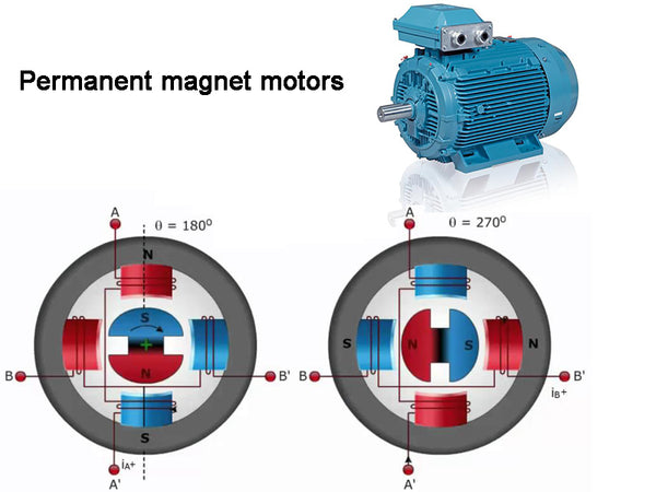
Permanent magnet motors (PM motors) use permanent magnets to generate air-gap flux, which replace the magnetic field coils in DC motors and the excitation body of the stator in induction motors. This structure cancels the excitation circuit and can reduce the copper loss of the rotor. Permanent magnet motors can be roughly divided into two categories, namely permanent magnet synchronous motors and permanent magnet brushless DC motors.
A permanent magnet synchronous motor (PMSM) is similar to an induction motor. The stator magnetic field rotates at a constant speed, and the induction waveform is sinusoidal, which can be vector controlled and transformed. The induced voltage generated by the permanent magnet brushless DC motor (PMBLDC) has a trapezoidal distribution, and the phase current has a rectangular or square waveform, so it is also called a square wave or electronic rectifier motor. The stator magnetic field changes in steps of square wave pulses. The following takes the permanent magnet synchronous motor as an example to illustrate its principle and structure.
There is a three-phase symmetrical sinusoidal distributed winding on the stator of the permanent magnet synchronous motor, which is similar to the winding of the AC motor. The magnetomotive force of the permanent magnet synchronous motor is generated by the permanent magnet, and the waveforms of the magnetomotive force, voltage and current are all sinusoidal waveforms.
Like DC motors and induction motors, permanent magnet synchronous motors also derive their power source from an electronic inverter. Due to the use of rare earth materials as permanent magnets, the magnetic flux density of the air gap is increased, so that the power density and torque-inertia ratio of the motor can be increased. With the assistance of high-resolution position sensor and current sensor, the motor can output smooth torque by adjusting the current of the motor.
Since the stator windings are symmetrically distributed, the sinusoidal currents in the three-phase windings of the stator can be balanced by adjusting the input voltage, thereby generating the magnetomotive force of the synchronous speed in the air gap. Through the feedback information of the rotor position sensor, the stator current can be adjusted, and the frequency of the stator current is consistent with the change of the rotor. By properly designing the shape of the permanent magnet, its magnetization direction can be controlled, the rotor magnetic flux changes sinusoidally, and the interaction of the stator and rotor magnetic fields generates an axial electromagnetic torque. Field weakening mode allows permanent magnet synchronous motors to run at higher speeds in the constant power region. The realization method is to make the magnetic flux of the stator and the magnetic flux of the rotor in opposite directions. The parameters of the motor, rated current, back EMF waveform and the maximum output waveform of the inverter all limit the maximum speed of the motor.
A high-performance motion control system requires a servo operating system. Permanent magnet synchronous motors are widely used in some fields due to their superior performance, fast torque response, robust structure, high power density and high efficiency. In the aerospace field, it is necessary to reduce the weight of the motor as much as possible on the premise of outputting the same power, and the permanent magnet synchronous motor can play an important role in these occasions.
A common problem with permanent magnet motors is the damage to the magnet chips.
The permanent magnets of permanent magnet synchronous motors are not only expensive but also temperature sensitive, which is the main disadvantage of permanent magnet motors. Permanent magnet synchronous motors are mostly used in small and medium power ranges, and are occasionally used in high-power applications.
According to the shape and position of the permanent magnet in the rotor, the permanent magnet synchronous motor can be divided into three types: surface-fixed type, embedded type and built-in type, as shown in Figure 3(a)~(c) respectively.
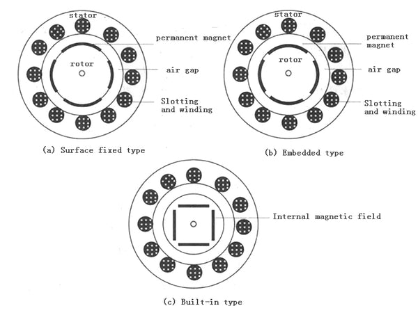
Figure 3 Permanent magnet motor
Surface-fixed and embedded permanent magnet synchronous motors are collectively referred to as surface-mounted permanent magnet synchronous motors. As shown in Figure 3(a), the permanent magnets in the surface-mounted PMSM are fixed on the surface of the cylindrical rotor using epoxy adhesive or wedge blocks, and the permanent magnets are wrapped by non-magnetic stainless steel or carbon fiber sleeves . The mechanical strength of this type of rotor mainly depends on the strength of the epoxy adhesive, but its manufacturing process is relatively simple. As shown in Figure 3(b), the permanent magnets of the embedded permanent magnet synchronous motor are embedded in the grooves on the rotor surface, which can better protect the permanent magnets. As shown in Figure 3(c), the built-in permanent magnet synchronous motor places the permanent magnets inside the rotor. Its manufacturing process is relatively complicated and its cost is high.
The modeling and control of permanent magnet synchronous machines can use scalar and vector control methods. In scalar control, it is necessary to convert a three-phase abc system into an equivalent circuit for each phase. In vector control, the parameters of the three-phase system are converted into equivalent two-phase system parameters, and the amplitude and angle of the current are controllable. Three-phase abc reference direction (synchronous motor natural coordinate system) and imaginary two-phase aβ (synchronous motor stationary coordinate system) and dq reference direction (synchronous motor rotor geometric axis coordinate system). In the dq coordinate system, d represents the axial direction of the center line of the rotor N pole or S pole, which is called the longitudinal axis or straight axis of the rotor, and q represents the direction with a space angle of 90° from the longitudinal axis, which is called the quadrature axis or the horizontal axis. axis. The abc and aβ reference coordinate systems are located on the stator, where the α axis is in the same direction as the a axis, and the α axis and the β axis form an included angle of 90°. The transformation of abc space into αβ space is mainly for the transformation of three-phase fixed parameters into two-phase fixed parameters. In the dq reference space, the d axis represents the direction of the magnetic flux, and the q axis forms an included angle of 90° with it.
Permanent magnet synchronous motors can be controlled by controlling the inductance in the direct and quadrature directions. For the surface-fixed permanent magnet synchronous motor, since the magnetic permeability of the magnetic circuit between the stator and the rotor around the stator is the same, the two inductances generated are also the same. Since the permeability of permanent magnets is the same as that of air, the magnetic circuit is consistent despite the presence of permanent magnets. The space occupied by the installation of the permanent magnets increases the radial distance of the effective air gap, thus making the self-inductance of the permanent magnet synchronous motor negligible.
The inductance of the built-in permanent magnet synchronous motor is different between the quadrature and the direct axis. Although the length of the air gap between the stator and the rotor is the same, the position space of the direct axis contains the permanent magnet, and the space of the quadrature axis contains the rotor, so the reluctance generated in the lateral and orthogonal directions is not equal. . The d-axis magnetic circuit contains a longer air gap, and the q-axis inductance Lq is higher than the d-axis Ld, so it has a higher impedance. Among them, self-inductance includes magnetizing self-inductance and leakage inductance, as follows:
Lq=Lls+Lmq and Ld=Lls+Lmd
Since the built-in permanent magnet synchronous motor places permanent magnets in the rotor, the height difference between Lq and Ld can make the built-in permanent magnet synchronous motor more suitable for field weakening operation. Therefore, compared with other typical permanent magnet synchronous motors, it has A wider constant power range. For electric and hybrid vehicles, this advantage is especially pronounced when the transmission is eliminated. Since the reluctance of the direct axis and the quadrature axis are not the same, there is a reluctance torque in the built-in and embedded permanent magnet synchronous motors.
Permanent magnet motors have fully considered the protection of permanent magnets in the design stage. Therefore, most permanent magnet motors can withstand considerable overload currents (usually 2 to 4 times the rated current) without damaging the permanent magnets.
5. Switched Reluctance Motor
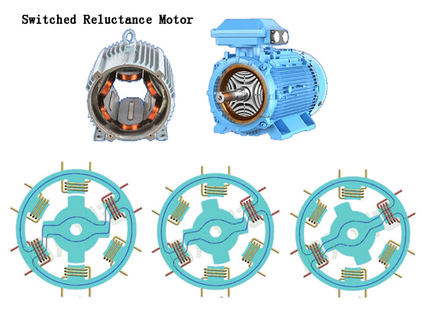
The switched reluctance motor is a doubly salient structure, each phase has an independent winding, and is a unilateral excitation motor. Both the stator and the rotor are made of stacked magnetic steel sheets, and there are no windings and permanent magnets in the rotor. Switched reluctance motors can be of many different types due to the variety of pole counts and sizes of rotors and stators. Figure 4 shows a four-phase cross-sectional view of an 8/6-pole and 12/8-pole three-phase switched reluctance motor. A 12/8 three-phase switched reluctance motor is a superposition of a 6/4-pole three-phase switched reluctance motor with a single-stator structure. One phase of the motor is formed by connecting opposite two-pole stator windings in parallel or in series. Usually, the 6/4 three-phase switched reluctance motor is called a two-stage (two-phase) motor, and the 12/8-pole three-phase switched reluctance motor is called a four-stage (four-phase) motor. When a certain phase of the stator is energized, in order to reduce the impedance of the magnetic circuit, the rotor salient pole closest to the stator salient pole will move towards it. Therefore, the switched reluctance motor can generate a clockwise (counterclockwise) constant torque if it is energized sequentially in the phase sequence.
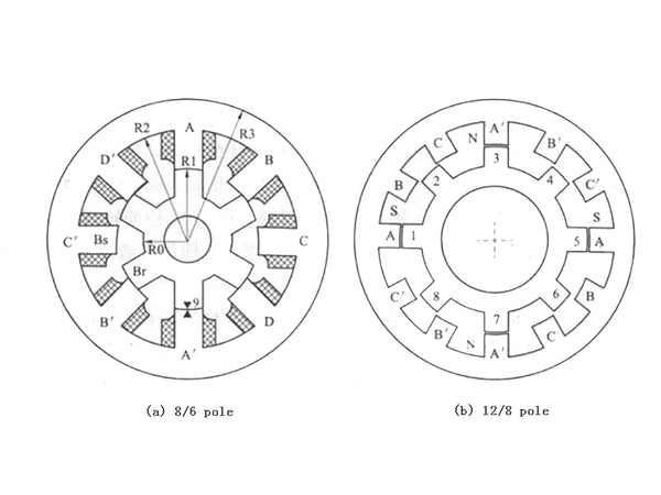
Figure 4 Schematic diagram of the cross-section of the three-phase switched reluctance motor
When the rotor and stator salient poles of a certain phase are completely aligned, the minimum magnetic resistance is generated at this time, which is defined as the alignment position of the phase. At this time, the value of the phase unsaturated inductance (La) is the largest. With the rotation of the rotor salient pole of this phase, the unsaturated inductance value gradually decreases. When the salient poles of the rotor of a certain phase and the salient poles of the stator do not coincide, it is called a non-aligned position. At this time, the inductance value (La) of the phase is the smallest. Although the concept of using inductance may not be adequate for highly saturated motors, such as switched reluctance motors, the unsaturated inductance at the aligned and non-aligned locations are two key reference locations for the controller.
Switched reluctance motors also have other types of stator/rotor pole number structures, such as 10/4 poles, 4/2 poles or 2/2 poles, but the disadvantage of these structures is that when the stator and rotor positions are completely aligned On time, starting torque cannot be generated, and there is a dead point (zero torque point). Motors with a high-ratio stator/rotor pole combination have low torque ripple and will not have the problem of zero starting torque.
Switched reluctance motors have some unique features that make them the biggest contenders for both DC and AC motors when it comes to variable frequency speed regulation and servo applications. Since there are no permanent magnets and rotor windings, the structure of the switched reluctance motor can be simplified, and most of the motor losses occur on the stator, which is easier to cool. Since the high self-inductance does not generate large currents instantaneously, the switched reluctance motor has a high starting torque. In addition, the rotor of the switched reluctance motor also has the advantage of high temperature resistance. The switched reluctance motor has a wide constant power area, which can be used as a drive motor. In addition, switched reluctance motors have strong fault tolerance, which is not found in other AC motors. Since each phase winding is connected to the inverter in series, it is impossible for the switched reluctance-driven inverter to have a direct short-circuit fault. The stator phase windings are relatively independent, so when one or more phases of the motor fail, the motor will shut down safely without emergency stop.
Switched reluctance motors also have disadvantages, of which torque ripple and noise are the most serious. Compared with other motors, higher torque ripple is caused due to the doubly salient structure and the independent generation of distributed torque for each phase. High torque ripple will generate large fluctuating currents in the DC power supply, requiring a large filter capacitor. The doubly salient pole structure will generate a large working noise, and the noise is mainly caused by the resonance generated by the radial magnetic force and the circumferential structure of the stator. This problem has attracted the attention of relevant experts, and methods have been found to reduce torque ripple and noise. However, users of switched reluctance motors often do not care about their torque ripple and noise.
Since permanent magnets are not used, it not only increases the burden on the stator windings and the inverter, but also increases the power requirements of the inverter. Compared with permanent magnet brushless motors, the stator copper loss per unit is higher, and the corresponding efficiency and torque per amp are reduced. However, the maximum speed corresponding to the motor in the constant power region is not limited by the fixed magnetic flux. Therefore, the switched reluctance motor can extend the constant power region. Although in order to reduce the torque pulse, it is necessary to add related algorithms to the motor control. Compared with the directional control of the induction motor, the control of the switched reluctance motor is simpler.