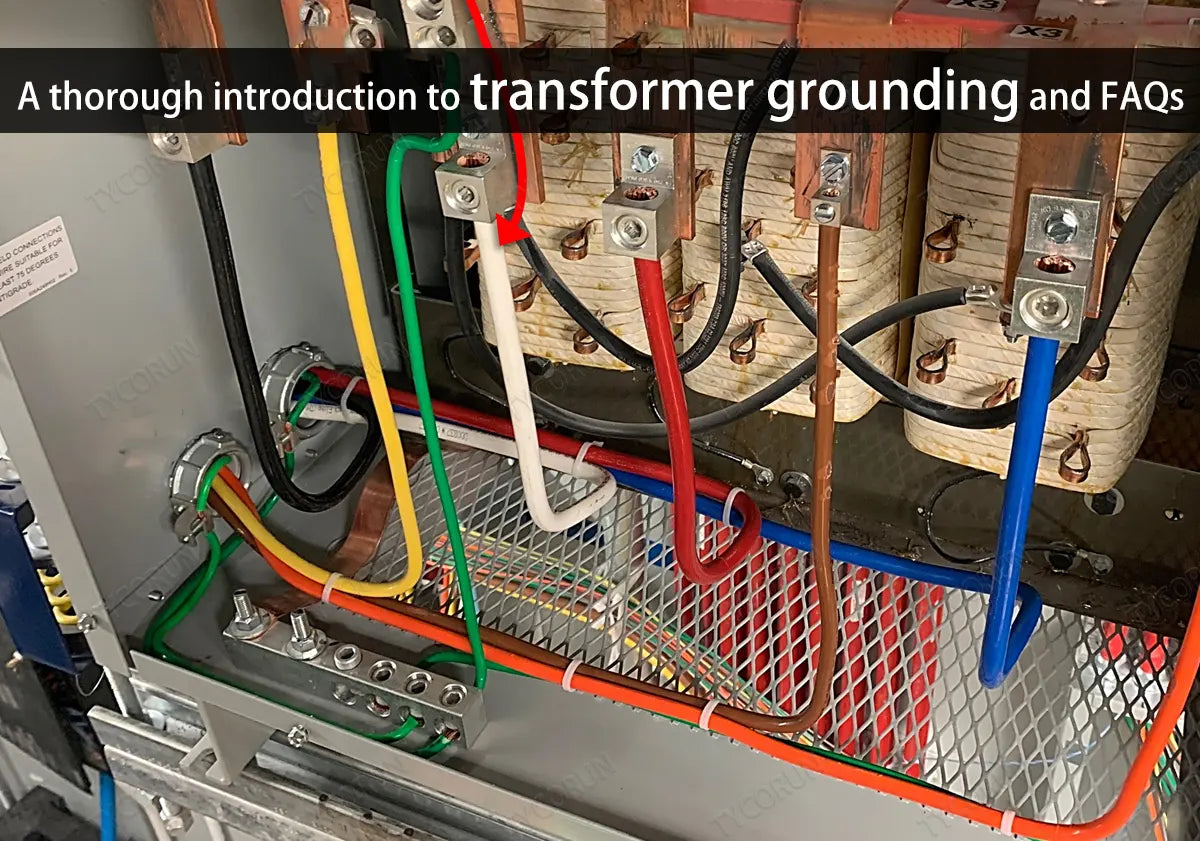
Unlike off grid batteries system that works with 500w inverter to 3000w inverter and LFP battery, when the transformer is in operation, the metal structure, parts, components of the iron core, fixed iron core, and windings are in a strong electric field. Under the action of the electric field, they have a high potential to the ground.
If the iron core is not grounded, a potential difference will occur between it and the grounded clamp and the fuel tank. Under the action of the potential difference, intermittent discharge may occur. Therefore, transformer grounding is of great significance for the safe use of transformers.
Main content:
- Why is transformer grounding necessary?
- Why can't the transformer be grounded at multiple points?
- Disadvantages of multi-point transformer grounding
- Why does transformer neutral point have to be grounded when the transformer is shut down?
- Neutral point gap grounding protection of transformer
- Grounding methods of transformer neutral point
- How to decide the number and location of neutral grounding
- FAQs of transformer grounding:
- How to switch the transformer neutral grounding
- Why does the neutral point grounding switch of the transformer adopt the method of first closing and then shutting down?
- When should a lightning arrester be installed at the neutral point of the transformer?
- Why must the neutral point of transformers of 110KV and above be grounded before power outage and power transmission?
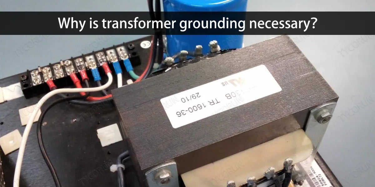
① Why is transformer grounding necessary?
When the transformer is in operation, there is a strong magnetic field around the winding. The iron core, metal structures, parts, components, etc. are all in a non-uniform magnetic field. Their distances from the winding are not equal. Therefore, the magnitude of the electromotive force generated by the magnetic field induction of components, components is also different, and there is also a potential difference between them.
Although the potential difference is not large, it can also break down a small insulation gap, which may also cause continuous trace discharge. Whether it is the intermittent discharge phenomenon that may occur due to the effect of potential difference, or the continuous trace discharge phenomenon that may cause breakdown of a small insulation gap, it is not allowed, and it is very difficult to inspect these intermittent discharge locations.
An effective solution is to reliably ground the metal structure, parts, components, etc. of the iron core, fixed iron core, and windings so that they are at the same earth potential as the fuel tank. The core of the transformer should be grounded at one point, and only at one point. Because the silicon steel sheets of the iron core are insulated from each other, this is to prevent the generation of large eddy currents. Therefore, all silicon steel sheets must not be grounded at multiple points. Otherwise, large eddy currents will be caused and the iron core will be damaged.
Although the silicon steel sheets are insulated, their insulation resistance value is very small. Uneven strong electric fields and strong magnetic fields can cause the high-voltage charges induced in the silicon steel sheets to flow from the transformer grounding point to the earth through the silicon steel sheets, but it can prevent eddy currents. Therefore, as long as any silicon steel sheet of the iron core is grounded, it is equivalent to grounding the entire iron core.
It should be noted that the core of the transformer grounding should be processed at one point, not two points, let alone multiple points, because multi-point transformer grounding is one of the common faults of transformers.
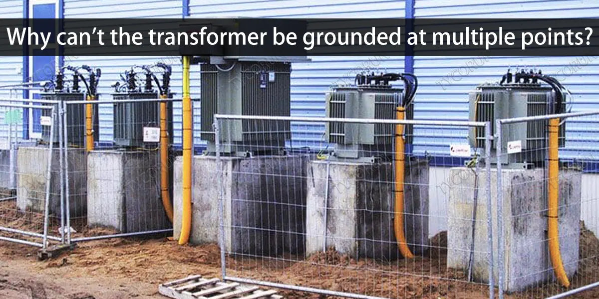
② Why can't the transformer be grounded at multiple points?
The reason why the transformer grounding can only be operated at one point is because if there are more than two points of transformer grounding, a loop may form between the transformer grounding points. When the main magnetic track passes through this closed loop, a circulating current will be generated in it, causing internal overheating and causing an accident.
The melted partial iron core will cause a short circuit fault between the iron chips, causing the iron loss to increase, which will seriously affect the performance and normal operation of the transformer. The iron core silicon steel sheet can only be replaced to repaired in this case. Therefore, the transformer grounding is not allowed to be processed at multiple points.
③ Disadvantages of multi-point transformer grounding
It is easy to form circulation and generate heat easily. During the operation of the transformer, its iron core and clamps and other metal parts are in a strong electric field, because electrostatic induction will generate a floating potential on the iron core and metal parts, and this potential will discharge to the ground, which is not allowed.
Therefore, the iron core and its clamps must be correctly and reliably grounded (except for through-bolts only). The iron core only allows one point to be grounded. If there are two or more points of transformer grounding, the iron core will form a closed loop with the ground point and the earth. When the transformer is running, magnetic flux will pass through this closed loop, causing circulating current, thus causing local overheating of the iron core and even burning of metal parts and insulation layers.
④ Why does transformer neutral point have to be grounded when the transformer is shut down?
This is mainly a measure taken to prevent over-voltage damage to the transformer.
For a power-receiving transformer with power supply on one side:
When its circuit breaker is not open or closed in all phases, if its neutral point is not grounded, there will be the following dangers:
- The neutral-to-ground voltage on the power side of the transformer can reach a maximum phase voltage, which may damage the transformer insulation.
- When there is capacitance between the high and low voltage windings of the transformer, this capacitance will cause transmission overvoltage from high voltage to low voltage.
- When the high-voltage and low-voltage windings of the transformer are capacitively coupled and the voltage on the low-voltage side reaches resonant conditions, resonant overvoltage may occur and damage the insulation.
For power transmission transformers with power supply on the low voltage side:
Since there is a power supply on the low-voltage side, a single-phase transformer grounding occurs on the high-voltage side of the transformer before it is integrated into the system. If the neutral point is not grounded, the neutral point-to-ground voltage will be the phase voltage, which may damage the transformer insulation.
When non-all phases are integrated into the system, when one phase is connected to the system, due to the different frequencies of the generator and the system, and the neutral point is not grounded for transformer grounding, the maximum voltage between the neutral point of the transformer and the ground will be twice the phase voltage. The combined voltage can reach up to 2.73 times the phase voltage, which will cause insulation damage.
Most of the systems above 110KV are systems with a directly grounded neutral point. The neutral point of the main transformer has a grounding blade switch. In order to ensure the sensitivity of the protection device, the neutral point of transformer grounding blade switch of the main transformer is always open during operation; but when the main transformer is operating, in order to prevent the overvoltage generated during operation from affecting the main transformer insulation, the transformer grounding switch must be closed.
Because overvoltage caused by non-synchronous operation of circuit breakers will endanger the insulation of these transformers, it is required that the neutral point of transformer grounding be directly grounded when switching on and off no-load transformers of 110kV and a bove. The transformer is an inductive component. After the voltage is instantly reduced, an instantaneous high voltage will be generated inside it. So for safety, the neutral point should be grounded.
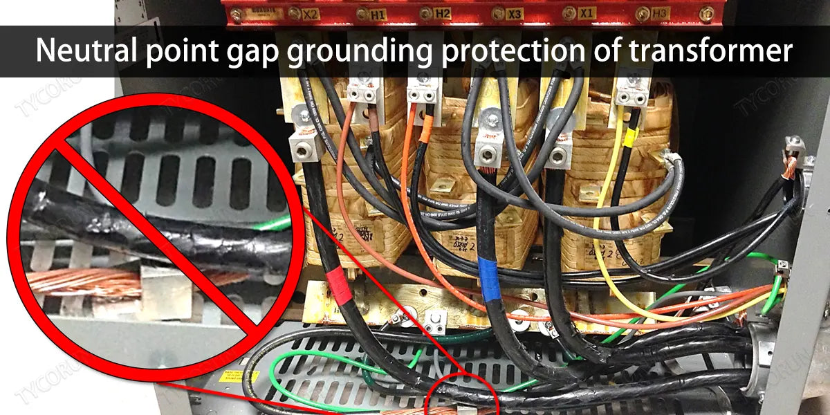
⑤ Neutral point gap grounding protection of transformer
The neutral point gap grounding protection of the transformer adopts the parallel connection method of zero sequence current relay and zero sequence voltage relay, with a time limit of 0.5S. When a ground fault occurs in the system and there is a zero-sequence current during discharge in the discharge gap, the zero-sequence current relay of the dedicated current transformer located at the grounded end of the discharge gap is activated.
If the discharge gap does not discharge, the zero-sequence voltage relay is activated. When a gap arc grounding occurs, the time element shared by the gap protection must not return halfway to ensure reliable action of the gap protection of transformer grounding.
⑥ Grounding methods of transformer neutral point
The arrangement of the transformer neutral point transformer grounding method should try to keep the zero sequence impedance of the substation basically unchanged. When encountering a special operating mode in which the zero-sequence impedance of the substation changes significantly due to transformer maintenance or other reasons, temporary handling should be carried out according to regulations or actual conditions.
- If there is only one transformer in the substation layout:
The neutral point should be directly grounded for transformer grounding. When calculating the normal protection setting, only the normal operation mode of the transformer neutral point being grounded can be considered. When the transformer is inspected, special operation methods can be implemented, such as changing the setting value or deactivating and activating the relevant protection sections according to regulations.
- If there are two or more transformers in a substation:
Only one transformer should be operated with its neutral point directly grounded for transformer grounding. When the transformer is out of service, the other transformer with an ungrounded neutral point should be changed to directly grounded. If the substation is normal, there must be two transformers with directly grounded neutral points. When one of the transformers with directly grounded neutral points is out of service, if there is a third transformer, change the third transformer to a directly grounded neutral point. Otherwise, handle it in special operation mode.
- If there are three or more transformers in a double-busbar substation:
They should be operated with the neutral points of the two transformers directly grounded for transformer grounding, and they should be connected to different busbars. When one of the transformers with a directly grounded neutral point is out of service, connect another ungrounded neutral transformer to ground directly. If it is not possible to maintain a transformer grounding point on different buses, it will be treated as a special operation mode.
In order to improve the protection cooperation relationship, when a short line is out of service for maintenance, the number of neutral point grounding transformers can be increased to offset the impact of the line outage on the zero-sequence current distribution relationship. The neutral point of auto transformers and transformers with insulation requirements must be directly grounded for transformer grounding.
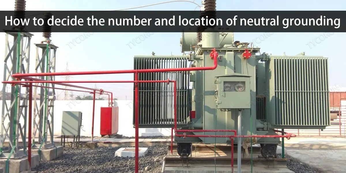
⑦ How to decide the number and location of neutral grounding
The number and location of neutral point transformer grounding should be set according to the requirements of relay protection, and the following should be taken into consideration:
- Insulation requirements of the transformer itself.
- In a large current directly grounded system, at least one transformer neutral point should be grounded on the power supply side (large condensers are considered in terms of power supply).
- If the two-winding or three-winding transformer in operation is a directly grounded system and the switch on one side is disconnected, the neutral point of transformer grounding blade on that side should be closed.
- If the neutral point grounding blade of a running box-type transformer needs to be switched, the neutral point grounding blade of the other transformer should be closed first, and then the neutral point grounding blade of the original transformer should be opened.
- When the transformer of 110kV and above is in hot standby state (as soon as the switch is closed, the transformer can be energized), its neutral point grounding blade should be closed.
- Transformers that are newly put into production or after overhaul should be phased when put into operation. The voltage should be boosted from zero as much as possible. For those that constitute a loop operation or need to be closed or broken, the inspection should be carried out.
FAQs of transformer grounding:
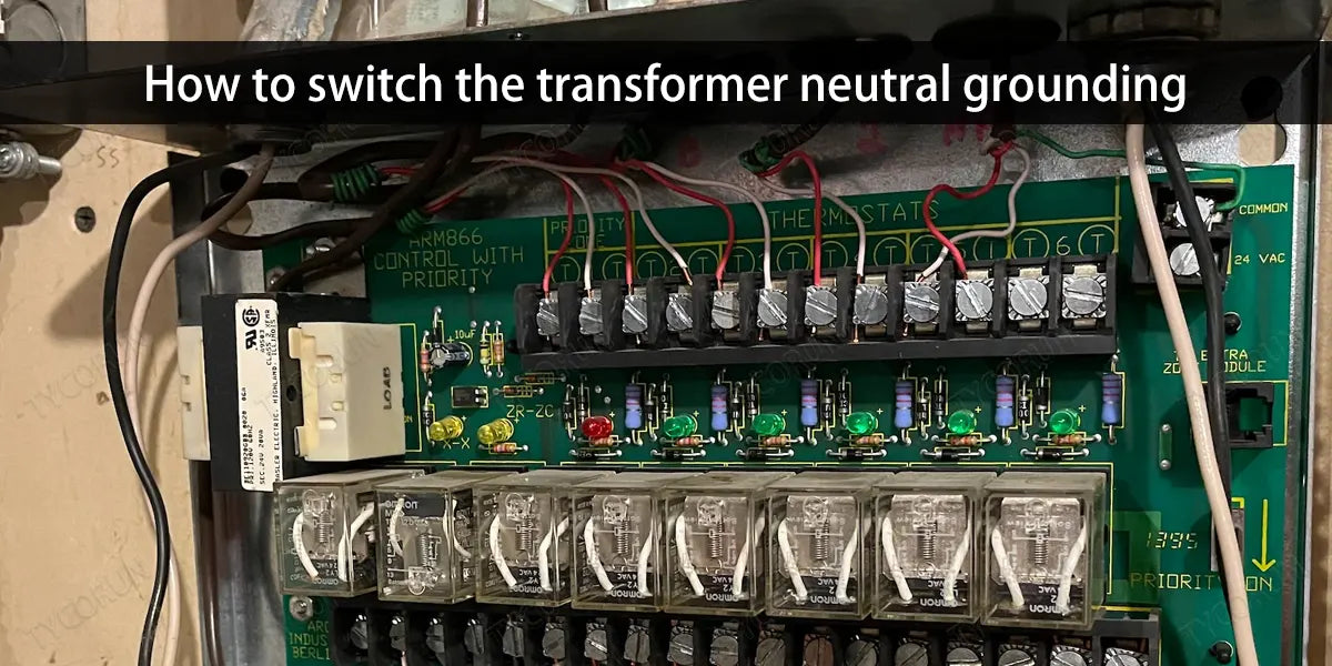
① How to switch the transformer neutral grounding
The switching principle is to ensure that the power grid does not lose its transformer grounding point, and the operation method should be closing first and then pulling:
a) Close the isolating switch of the backup transformer grounding point.
b) Open the isolating switch of the working ground point.
c) Switch the zero sequence protection to the transformer with the neutral point grounded.
② Why does the neutral point grounding switch of the transformer adopt the method of first closing and then shutting down?
Because the circuit breaker on the high-voltage side of the main transformer is generally operated in separate phases, it is easy for the circuit breaker in separate-phase operation to fail to close or open the three phases when opening and closing. This may cause zero-sequence overvoltage on the high-voltage side, causing transmission problems.
After being connected to the low-voltage side, it is easy to cause insulation damage to the low-voltage winding. If the transformer grounding isolating switch is closed before operation, it can effectively limit overvoltage and protect the insulation.
First closing and then shutting down refers to the method that if the main transformer neutral point switch is turned off, the gap protection should be turned on first, and then the neutral point should be turned on and then the zero sequence protection should be turned off.
Conversely, to close the neutral point switch of the main transformer, the zero sequence protection of the main transformer must be turned on first, and then the gap protection must be turned off after turning on the neutral point. This is to prevent the busbar where the main transformer is located from losing transformer grounding protection.
③ When should a lightning arrester be installed at the neutral point of the transformer?
In a power grid with a directly grounded neutral point, some transformers have a neutral point that is not grounded. When a three-phase lightning wave invades, the voltage of the neutral point is very high (up to 190% of the voltage amplitude at the incoming line terminal).
If the neutral point insulation is not designed according to the line voltage, a lightning arrester should be installed at the neutral point to limit the neutral point overvoltage amplitude and protect the neutral point insulation.
④ Why must the neutral point of transformers of 110KV and above be grounded before power outage and power transmission?
During operation, in order to meet the sensitivity coordination requirements of relay protection devices, the neutral points of some transformers are operated without grounding. However, because overvoltage caused by non-synchronous operation of circuit breakers will endanger the insulation of these transformers, it is required that the neutral point of the transformer be directly grounded when switching on and off no-load transformers of 110KV and above.
Related posts: backup power supply for home, high voltage switchgear, low voltage power distribution system