Main content:
1.Basic principles of supercapacitor
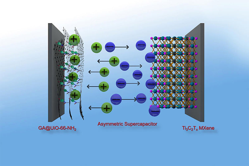
In order to define the supercapacitor and summarize its characteristics and basic parameters, the basic operation principle of the supercapacitor is given in the figure below.
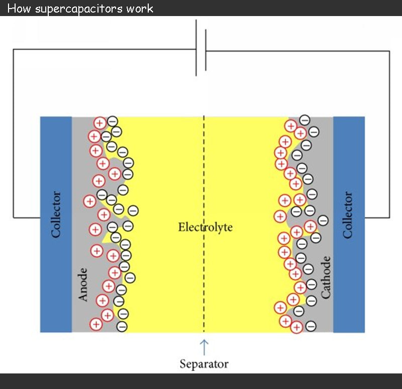
Supercapacitor consists of two electrodes separated by a separator soaked in an electrolyte.
The two electrodes of supercapacitor is formed by depositing a porous material on a thin metal film, usually aluminum, and carbon (activated carbon) is a commonly used porous material. When charged, the supercapacitor's charge is stored at the interface between the porous material and the electrolyte. The use of activated carbon provides a very large active surface for charge storage with good electrical conductivity.
The role of the supercapacitor electrolyte is to ensure the mobility of internal ions to the electrodes. Anions should be free to migrate to the positive electrode, and similarly, cations should be free to migrate to the negative electrode. Electrolytes can be solid, but are mostly liquid. The choice of electrolyte is often the result of a compromise between supercapacitor cell voltage and ionic conductivity, and the pursuit of maximizing ionic conductivity may lead to the chosen electrolyte decomposition voltage as low as 1 V. Since the redox reaction will lead to irreversible reactions during the charge and discharge phases, the operating voltage of the supercapacitor must be limited (2.5 ~ 3V).
The separator of a supercapacitor is usually a piece of paper, which acts as an insulation and prevents any conductive contact between the electrodes. However, it must be able to soak in the electrolyte and not affect the ionic conductivity of the electrolyte.
The two main parameters that affect the energy density of supercapacitor is the maximum allowable terminal voltage and capacitance.
As previously introduced, the maximum terminal voltage of a supercapacitor is related to the electrolyte chosen. Currently used electrolytes can provide terminal voltages of 2.5~3V. If the ionic conductivity is affected at a terminal voltage of 3V, the voltage needs to be reduced accordingly.
The capacitance of supercapacitor can range from a few farads to thousands of farads. The capacitance value is calculated based on the basic principle of supercapacitor, that is, the electric double layer structure invented by Helmholtz in 1879, as shown in the figure below.
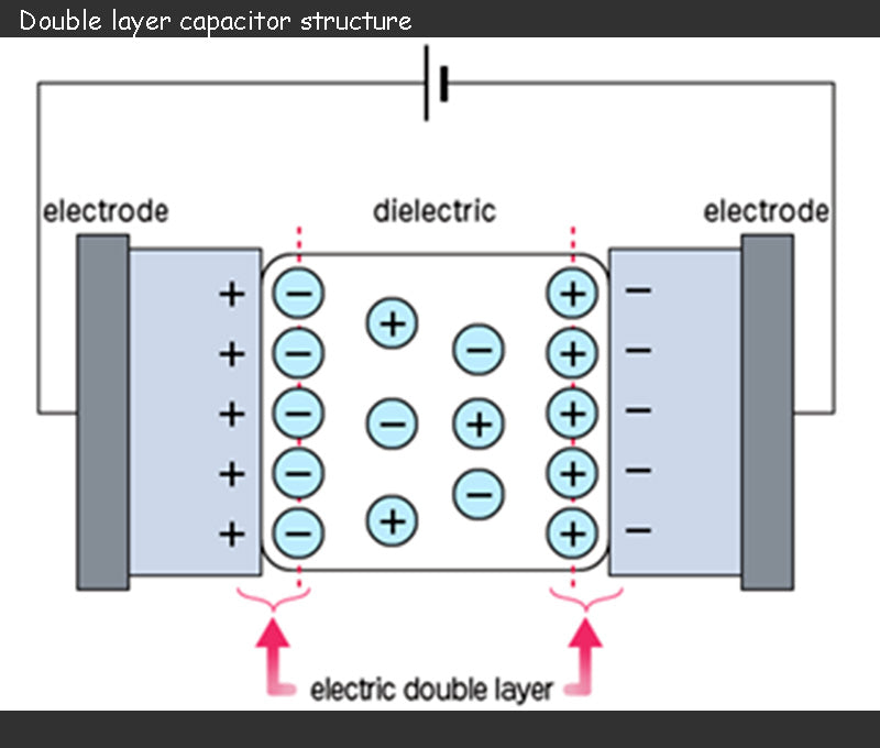
During charging, the anions in the electrolyte of the supercapacitor are attracted to move toward the positive electrode, and the cations move toward the negative electrode, and an electric double layer is formed at the interface between each electrode and the electrolyte. That is to say, the charge accumulation process of different electrical layers is different: positive charges and anions are attached to the positive electrode, and negative charges and cations are attached to the negative electrode. These two electrical layers produce a capacitance as shown in the following equation:

In the formula, Cdc is the capacitance value of an electric double layer capacitor; ε is the dielectric constant; A is the effective surface area of the electrode; d is the equivalent distance between the two plates similar to a traditional capacitor.
The primary factor that can explain such a huge capacitance value of supercapacitor energy storage technology is the use of porous activated carbon material in the electrode, which greatly increases the effective surface area A of the electrode and can provide considerable charge storage capacity (3000m2/g). Conversely, the equivalent distance d is determined by the size of the anions attached to the positive electrode and the size of the cations attached to the negative electrode. In general, d is between 2×10⁻¹⁰m and 10×10-10m. It can be seen from the above formula that the capacitance value of the electric double layer capacitor is inversely proportional to d, which further increases its capacitance value.
Therefore, we can think of a supercapacitor as two capacitors connected in series, and the two capacitors represent the electrical layers on the two electrodes, respectively. The equivalent capacitance value is related to the effective surface area of the two electrodes (which is increased due to the use of porous materials) and the size of the anion and cation, which can be as high as kilofarads. Finally, we must remember that the maximum allowable voltage of a supercapacitor is determined by the electrolyte chosen, which is generally 2~3V.
2.Supercapacitor Model - Main Parameters
There are generally two modeling approaches for supercapacitor, modeling using equivalent circuits and modeling using impedance spectra. The benefit of equivalent circuit modeling is that previously defined parameters can be directly linked to the actual device. Moreover, the modeling process of the supercapacitor can also be directly linked to the actual operation, which we will explain later (mainly the capacity calculation and efficiency analysis of the supercapacitor bank)
The figure below shows the equivalent circuit model of the supercapacitor, which is also the most commonly used model.
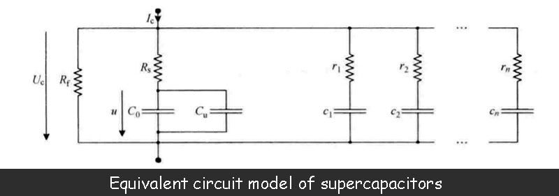
The capacitance value C0 is the main parameter of the supercapacitor. This value is equivalent to the series connection of two electric double layer capacitors defined by the above formula. The manufacturer can provide this parameter.
However, the measurement of the capacitance value of the supercapacitor shows that the value is not constant, but a function of the terminal voltage of the two electric double layers, that is, a function of the capacitor terminal voltage Uc. The reason why the capacitance value of a supercapacitor depends on the terminal voltage is related to the presence of two diffusion layers within the electrolyte, each of which is in direct contact with its respective adjacent electric double layer. Characteristics of the diffusion layer include the size of the volume, the density of anions, the density of cations, and the temperature of the electrolyte. In addition, the potential difference between the terminals of the electric double layer is also related to the diffusion layer, which directly affects the volume of the diffusion layer. Each diffusion layer has a capacitance value that is inversely proportional to its volume. When the terminal voltage of the supercapacitor increases, the volume of the diffusion layer decreases accordingly, resulting in an increase in its capacitance value. This phenomenon can be illustrated by the variable capacitance Cu in the equivalent circuit model, whose value is a function of the voltage u.
In fact, the capacitance value C of a supercapacitor can be defined by the following relationship:

In the formula, C0 is the basic capacitance value determined by the two electric double layers; u is the terminal voltage of the two electric double layers; K is the variable constant of the capacitance value Cu. For some supercapacitors, at the maximum voltage (such as 2.5V), the capacitance value Cu can reach 25% of the basic capacitance value C0
In the figure above, Rs is the series resistance of the supercapacitor. Its value depends in part on the properties of the porous material deposited on the metal plate in the electrode, but is mainly determined by the ionic conductivity of the electrolyte. In fact, the analysis of the supercapacitor's electromotive force in the image above shows that during its charge-discharge phase (shown as the charging phase in the image above), a voltage drop occurs in the electrolyte. When the supercapacitor is placed, the voltage drop within the electrolyte of the supercapacitor should be zero, but only if the relevant effect of the diffusion layer is not considered. The value of the series resistance Rs is generally between 0.5~100mΩ, and the manufacturer can provide this parameter.
In the above figure, Rf determines the leakage current of the supercapacitor, which is larger than the leakage current of the battery. This value is mainly related to the conductivity of the separator and is also affected by the impurities contained in the electrolyte. When the capacitor is charged beyond the maximum allowable voltage (the decomposition voltage of the electrolyte, mainly caused by the redox reactions occurring at the interface of porous material and electrolyte), the impedance Rf will decrease. Rf is usually 500Ω~100kΩ. Manufacturers generally do not give the size of this value, but provide a data of leakage current under the maximum voltage, which is generally 40μA ~ 10mA.
In addition to the main parameters of the supercapacitor given above, the equivalent circuit model shown above adds a series of parallel RC units (r1c1,…,rncn). These cells reflect charge redistribution phenomena or dielectric relaxation processes with time constants typically ranging from seconds to hours, or even longer. This charge redistribution means that, due to the ultra-high porosity of the activated carbon, the stored charge is transferred from the easily accessible area of the electrode to the restricted area. Therefore, during the fast charging phase of the supercapacitor, the charge on the electrodes exhibits an uneven distribution. When charging is complete, the charges move freely on the electrodes, and after a number of time constants, finally present a uniform distribution.
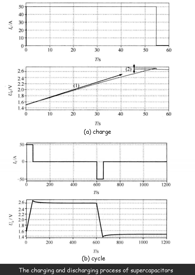
The figure below shows the terminal voltage U of the supercapacitor at a given charge/discharge current. change process, process. The supercapacitor used is 1500F/2.7V, and its actual performance is consistent with the model.
The supercapacitor is charged and discharged with constant current, and the following figure shows the dependence of the capacitance value on the terminal voltage. Compared to curve (1), the voltage in the graph does not increase linearly. Not only that, the curve (2) in the figure shows that due to the existence of the series resistance Rs, when the charging stops, the terminal voltage Uc of the supercapacitor will have a sudden drop.
The figure below shows a complete charge/discharge cycle of a supercapacitor. When the charging of the supercapacitor is complete, and after the voltage drop phase caused by the series resistance, there is still a significant drop in terminal voltage, which is not caused by leakage current, but caused by relaxation phenomenon: the charge moves freely on both electrodes to achieve uniform The process of distribution results in a certain voltage drop, but this voltage drop does not generate energy losses. This phenomenon also occurs after the capacitor is discharged. Even if the current is discharged to zero, the voltage will rise due to the relaxation phenomenon.
Manufacturers generally do not provide parameters related to relaxation phenomena, even if they are useful. Regardless of whether the supercapacitor charging process is completed in minutes or hours, the actual stored energy of the supercapacitor due to relaxation phenomena is more than measured by its nominal capacitance value. However, this extra capacitance is difficult to utilize, especially when the supercapacitor is cycled with a time constant on the order of minutes. Therefore, the stored energy related to relaxation capacitance is generally not considered.
In fact, in the supercapacitor equivalent circuit model shown above, the RC relaxation circuit can usually be omitted.
3.Thermal Model of Supercapacitor
It can be seen from the equivalent circuit model that there is a series impedance in the supercapacitor. Although its value is very small, losses will still occur during the charging and discharging process, that is, energy dissipation due to the Joule effect. Therefore, the supercapacitor will have a temperature rise during operation, which needs to be quantified to determine whether the temperature rise can be tolerated or should be cooled with the help of a cooling system.
Precisely defining a thermal model of a supercapacitor is difficult because it requires an accurate grasp of the device's internal structure, which manufacturers are often reluctant to provide. At the user's request, the manufacturer should provide a special tool to calculate the calorific value of the device. However, these tools tend to be closed and based on undisclosed mathematical models. Therefore, in most cases, we can only rely on the "Blackberry" model and use a small number of parameters provided by the manufacturer to estimate those parameters that are not given. The parameters they provide include the thermal conductivity of the device and its densities (bulk density and mass density), but generally do not include the thermal capacity of the device, but this can be obtained by appropriate measurement or estimation.
Given that the supercapacitor's operating mechanism and components are known, the overall thermal capacitance of the device can be estimated from the thermal capacitance of each component. For example, for a device containing 65% aluminum (900J/kg/K), 25% carbon (900J/kg/K), and 10% (4180J/kg/K) electrolyte, the overall heat capacity is calculated to be 1203J /kg/K.
Therefore, the thermal performance of the supercapacitor device can be determined by calculating the thermal conductivity, compositional density and heat capacity through finite element numerical analysis software. The figure below shows an example of a 2D simulation.
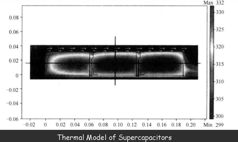
In this example, three supercapacitor is placed on the same printed circuit board and housed in a carbon fiber box that is open on both sides. The top of the box is exposed to sunlight (1kW/m2) and air blows from left to right at a constant speed (0.5m/s). At the same time, each supercapacitor is cyclically charged and discharged, so that the loss of the charge-discharge current on the series impedance reaches 1.13W, and each charge-discharge cycle is 2400s.
The results in the figure above show the heating process of the three devices in the supercapacitor, but this method of measuring the surface temperature of the device is not accurate because the temperature inside it will be higher.
It should be noted that the above model is just a global model. The premise is that the losses inside the device are uniformly distributed, and the device itself is also considered to be homogeneous. Although not strictly true, such a model of a supercapacitor is very close to the real characteristics of the device.
Read more: Introduction of battery technology