
main content:
- Basic requirements for lithium-ion battery protectors
- 1. Protector for single-cell lithium-ion battery
- 2.3~4 Lithium-ion battery protection
In order to prevent overcharging of lithium-ion batteries, lithium-ion batteries must be designed with protection circuits, and lithium-ion battery protector ICs are suitable for single-cell and 2~4-cell battery packs. The requirements of the protector are introduced here, and the circuit protector of the single-cell lithium-ion battery circuit is also introduced.
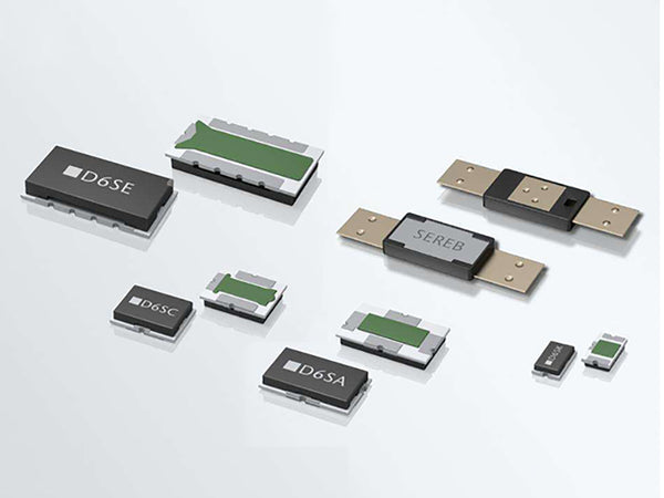 Lithium-ion battery protector
The basic requirements for lithium-ion battery protectors are as follows:
①It must be fully charged when charging, and the accuracy of the termination charging voltage is required to be about ±1%;
②There is no current during charging and discharging, and short-circuit protection should be designed;
③It is forbidden to continue discharging when the termination discharge voltage is reached, and the termination discharge voltage accuracy is controlled at about ±3%;
④Pre-charge the deeply discharged battery (not lower than the termination discharge voltage) with a small current before charging;
⑤In order to ensure the stable and reliable operation of the battery and prevent the interference of transient voltage changes, the internal delay circuit should be designed with overcharge, overdischarge, and overcurrent protection to prevent transient interference from causing instability;
⑥ It saves power consumption (the protector should be energized when charging and discharging). The power consumption of a single-cell battery protector is generally less than 10μA, and the multi-cell battery pack is generally about 20μA; when it reaches the termination of discharge, it is in the off state, and generally consumes less than 24μA;
⑦The circuit of the protector is simple, the peripheral components are few, and it occupies a small space. Generally, it can be made in a battery or battery pack;
⑧The price of the protector is low.
1. Protector for single-cell lithium-ion battery
Now take the AIC1811 single-cell lithium-ion battery protector as an example to illustrate the circuit and working principle of the protector.
The main features of this device are: the termination charging voltage is 4.35V, 4.30V and 4.25V (represented by models A, B, and C), and the charging voltage accuracy is ±30mV (±0.7%). When the working voltage is 3.5V, it works The current is 7μA, and the power consumption is only 0.2μA after the discharge is terminated; there are overcharge, overdischarge, overcurrent protections, and a delay to avoid transient interference; overdischarge voltage 2.4V, accuracy ±3.5%; operating temperature ﹣20 ~+80℃.
During normal charging and discharging, both V1 and V2 are turned on. The charging current flows in from the cathode (+), charges the battery through the fuse, and flows out from the anode (-) after passing through V1 and V2. During normal discharge, the current flows from the + terminal through the load RL (not shown in Figure 1), through one terminal and V2, V1 to the negative electrode of the battery, and the direction of the current is opposite to the direction of the charging current. Since the on-resistance of V1 and V2 is extremely small, the loss is small. Refer to Figure 2 and Figure 3 for the working status of several protection circuits.
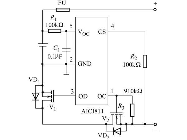 Figure 1 Schematic diagram of a single-cell lithium-ion battery protector circuit
(1) Overcharge protection
As shown in Figure 2, P1 is a comparator with hysteresis that controls overcharge. The voltage divider composed of R6 and R7 is connected to both ends of the lithium-ion battery. The voltage of the middle detection battery is connected to the non-inverting end of R1, and the inverting end of P1 is connected to the 1.2V reference voltage. When charging, when the battery voltage is lower than the overcharge threshold voltage, the inverting terminal voltage of P1 is greater than the non-inverting terminal voltage, P1 outputs a low level to turn on Q1, and the bias resistor R3 of V2 has a current flowing to make V2 also conductive. Turn on (V1 is turned on when charging), thus forming a charging loop. When the charging reaches and exceeds the charging threshold voltage, the voltage at the non-inverting terminal of P1 exceeds 1.2V, and P1 outputs a high level. After a 100ms delay, Q1 is cut off, R3 has no voltage to cut off V2, and the charging circuit is disconnected to prevent overcharging.
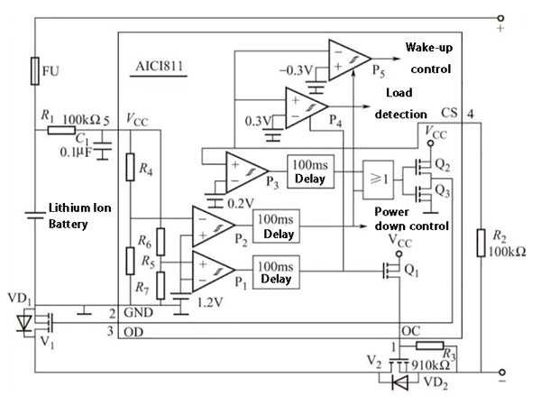 Figure 2 Schematic diagram of the working status of several protection circuits
(2) Over-discharge protection
The over-discharge protection circuit is composed of a voltage divider composed of R4 and R5, a comparator P2 with hysteresis, a 100ms delay circuit, an OR gate and a CMOS output circuit composed of Q2 and Q3. When the battery discharge reaches 2.4V, P2 outputs a high level, after a delay, OD outputs a low level, V1 is cut off, the discharge circuit is disconnected, and discharge is prohibited.
(3) Overcurrent protection
Taking the discharge current overcurrent protection as an example, the CS terminal is the discharge current detection terminal, which continuously detects the discharge current. This is because the voltage VCS at the CS terminal has a certain relationship with the discharge current IL, as shown in Figure 3. If the on-state V1 and V2 are regarded as a resistor, the discharge circuit is shown in Figure 3.
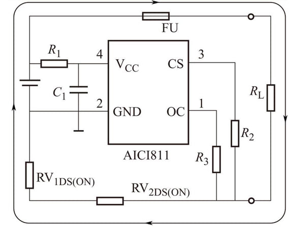
Figure 3 Single-cell lithium-ion battery overcurrent protection
The overcurrent protection circuit is composed of a comparator P3, a delay circuit or gate and so on. If the discharge current exceeds the set threshold and VCS exceeds 0.2V, P3 outputs a high level, and the result is the same as the over-discharge situation, which turns off V2 and prohibits discharging. Other functions of the device will not be introduced here.
2. Protection of 3~4 lithium-ion batteries
Now take MAX1894/MAX1924 as an example to illustrate its functions and features. MAX1894 is designed for use in 4-cell lithium ion battery packs, while MAX1924 is suitable for 3-cell or 4-cell battery packs. Two protectors can monitor the voltage of each battery in the series battery to avoid overcharging and overdischarging, which can effectively extend the life of the battery. In addition, it can also prevent excessive current or short circuit during charging and discharging.
The protector circuit composed of two devices is shown in Figure 4. It is a protector for 4-cell lithium-ion battery packs. The voltage of each of the four batteries connected in series is basically the same when charging (voltage equalization), so internal circuits and external resistors, capacitors and other components are added; in addition, it is controlled by a microcontroller (μC), which can output the battery status Signal makes the function more perfect.
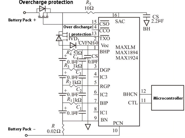
Figure 4 Schematic diagram of the protector circuit composed of two devices
The main features of the two devices are: the overvoltage threshold of each battery can be set, and the voltage accuracy can reach ±0.5%; the termination discharge voltage threshold can also be set, the accuracy can reach ±2%; there is a shutdown mode, and the shutdown state The hourly power consumption is 0.8μA, which can prevent the battery from being deeply discharged; the typical working current is 30μA; the working temperature range is -40~+85℃.