Main content:
1.Overall requirements of the air supply system
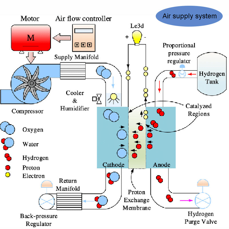
The primary purpose of the air supply system (or loop) is to supply the oxidant to the fuel cell cathode plenum. In the case of hydrogen fuel cells, the oxidant (pure oxygen or air) can be stored in a high-pressure vessel. However, for transportation (with the exception of submarines and space) the oxidant is usually supplied by outside air, both abundant and free. Although this oxidant supply method is relatively inexpensive, it is an air supply system that requires careful consideration. A few major issues to be aware of are as follows:
1) This air supply system must direct outside air (if the air matches the normal operating requirements of the fuel cell - which we will discuss later) to the reaction interface of the cathode plenum.
2) The outside air is usually polluted by various gases or particles (CO, dust, etc.), if injected into the fuel cell, it will reduce the performance or life of the cell.
3) Inhaled air needs to be "conditioned" for humidity and temperature, and in this way improves the performance of the battery (in some cases, improper humidity and temperature can indeed prevent the battery from operating completely).
Depending on the technology used, intake mode and battery power level, the PEMFC's air supply system can operate in three ways:
1) "Self-Breathing" Mode: As the name suggests, the fuel cell "breathes in" the surrounding air as needed, in relation to the current demand. The supply demand for electrical current stimulates the consumption of oxygen, which manifests itself in the supply circuit, causing a low pressure. This mode operates completely passively, so it is very simple, does not require any air supply system, and is suitable for very low power batteries (often less than 200W).
2) Atmospheric mode: The air pump or blower pump is used to supply air to the battery, and the operating pressure of the fuel cell is very limited (up to several hundred millibars).
3) Compression mode: This mode is generally recommended for batteries with a power greater than 1kW. It can be seen that the higher the gas partial pressure, the higher the electrochemical conversion efficiency. Therefore, this air supply system mode enables the battery to obtain high power density, and is also beneficial to the water and thermal management of the battery.
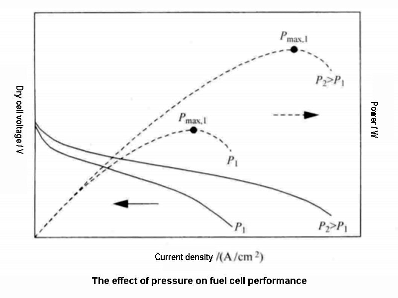
Compressed air can be obtained by a compressor driven by an electric motor, and can compress the air to different pressures (1.5~4bar absolute pressure).
2.Select a compressor suitable for the fuel cell air supply system
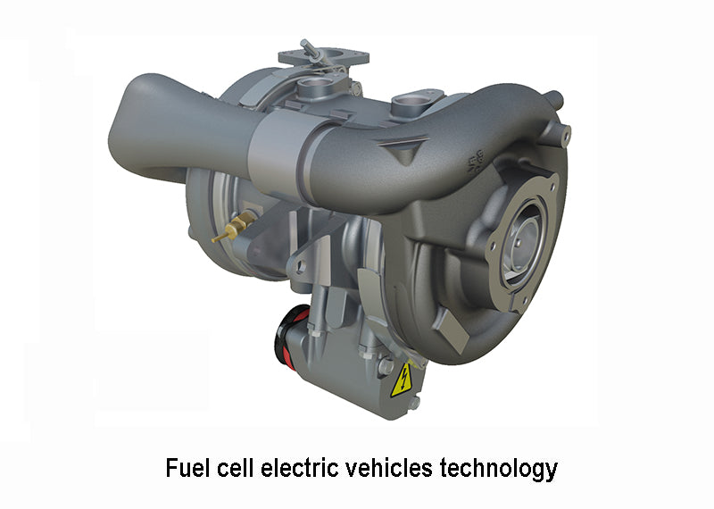
Compressors for air supply systems are available in a variety of technologies and the choice of air compressor generally depends on the desired air quality, pressure and displacement. Choose from the following compressors: Centrifugal Compressor, Dry Screw Compressor, Lubricated Screw Compressor, Rotary Vane Compressor, Sliding Vane Compressor, Lubricated Piston Compressor, Dry Piston Compressor compressors, helical compressors and scroll compressors. The most widely used are positive displacement compressors, which capture gas in a closed container and compress it through a gradual reduction in volume. The turbo compressor uses the rotational speed of the impeller to convert the kinetic energy of the gas into pressure.
The primary factor in the selection of a compressor for a fuel cell air supply system is the air quality at the compressor outlet. The electrochemical reactions that take place inside the fuel cell are strictly prohibited from entering the cell with suspended oil particles in the air. In fact, the residual oil droplets in the compressed air will coat the catalyst surface, which greatly reduces the performance of the battery and ultimately reduces the battery life. Unfortunately, most of the "off-the-shelf" compressors available today use oil for cooling or lubrication. In fact, if we want oil-free air, only compressors without lubrication or those lubricated with water (such as turbo compressors, dry screw, dry rotary vane, dry piston, dry helical or membrane compressor).
In this regard, water-lubricated compressors are clearly the best solution for fuel cell applications. In fact, this air supply technology has the advantage of maintaining lubricating properties, reducing mechanical losses, and quasi-isothermal compression processes. provide conditions. Since the air is more or less humidified before entering the fuel cell, this increases the adiabatic efficiency and reduces the size of the humidifier.
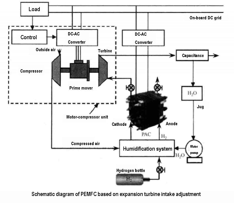
Second, conditions such as the air supply system, the amount of air required and the magnitude of the compressor power variation help determine the appropriate compression technique. If the strength is used, rotary compressors and turbo compressors are suitable, they require little maintenance but are therefore expensive. For fuel cell applications, high-speed compressors (above 10,000 r/min) such as centrifugal, scroll or screw compressors are attractive. In addition, a regulating valve (or turbine) can be mechanically (and ultimately directly) coupled with the motor-driven compressor shaft to recover some of the compression energy from the cathode outlet (low oxygen) gas. The schematic diagram of PEMFC based on expansion turbine intake adjustment is shown in the figure below.
In terms of efficiency, among all rotary compressors, screw, screw and membrane compressors are more suitable for fuel cell air supply systems (for low and medium power fuel cells) than piston or centrifugal compressors. These compressors are air-tight, meaning they are more volumetrically efficient than other rotary compressors (rotary vane, vane).
Last but not least, the air compressor should be tailored to the power range suitable for the fuel cell's air supply system. Currently, there are only a few prototype compressors specifically designed for small fuel cells. In general, these compressors suffer from one or more undesirable characteristics (i.e. mediocre efficiency, extremely high noise, lifetime mismatch with fuel cell systems, etc.). So, there is still a lot of work to be done in this regard.