Using a relay as the main circuit switch of a voltage regulator is a common method for photovoltaic power generation systems. It has the advantages of simple control, good isolation, and low price. However, due to the limited life of the relay contacts, easy ignition on and off, and the switching speed cannot be too fast, for some special occasions, such as high-voltage systems, high-current systems, etc., the use of relays is prone to problems. At this time, it is necessary to use contactless voltage regulators to complete the switching function of the main circuit. The development of modern power electronics technology has made contactless high-power switches possible, and there are many types of devices to choose from, such as high-power transistors, Darlington transistors, VMOS transistors, thyristor GTO, etc. The working principle of a contactless voltage regulators using thyristor as switching device of charging circuit.

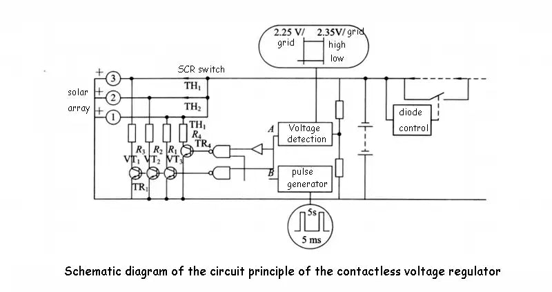
The following figure shows the schematic diagram of the circuit principle of a series-type incremental control contactless voltage regulators using thyristor as switching device. Here, the solar battery array is divided into several sub-arrays, and each sub-array has a thyristor. It can be used as a switch control device, and the contactless voltage regulators can also play the role of blocking diode at night to prevent the reverse current of the battery. Contactless voltage regulators VT1,VT2 and VT3
are level comparators with hysteresis. Assuming that the battery charging protection point is 2.35V/grid, the recovery charging point is 2.25V/grid. Then when the charging voltage of the battery reaches 2.35V/grid, the output point A of the contactless voltage regulators is the output level. At this time, when the pulse generator jumps up the pulse, it can be reversed to the transistor through the NAND gate. On the base of the battery, TR1 is turned on, the first sub-array is short-circuited, and the reverse current of the battery controls the first sub-array, that is, the thyristor TH1 is turned off, so that the first sub-array stops charging. If the battery voltage is between 2.35V/div ~ 2.25V/div, the pulse will always be only applied to the base of TR1. When the battery voltage is reduced to less than 2.25V/div, the output state of the contactless voltage regulators change to a low level. After inversion, the NAND gate is added to the base, so that when the next When the pulse arrives, TR1 is turned on, and the thyristor is triggered to turn on again, so that the first sub-array can be charged again.

Generally speaking, each sub-array control of the circuit of this contactless voltage regulators are relatively independent, and the voltage control point of each sub-array can be set to the same value, but due to the control of all contactless voltage regulators. It is impossible for the voltage points to be set exactly the same, so the action process will also be carried out first and then due to this slight difference.
In addition, using the method of adding diodes can easily perform contactless voltage regulators regulation on the required output voltage. By adding a diode, the output voltage drops by 0.7V, and the series connection of several diodes can make the power supply voltage of the battery drop to within the maximum power supply voltage range required by the load equipment. Usually the diode step-down control is also completed by the voltage detection circuit with hysteresis. Using relays as control switches on the way is the easiest way to control loads.
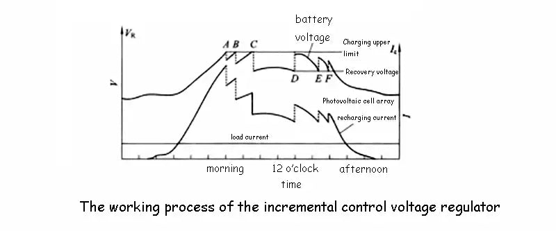
The following figure is a working characteristic diagram of the actual charging contactless voltage regulators of a 5-way sub-array, of which 4 can be adjusted and controlled, and the parameters of this system have been given in the figure. When the battery is close to being fully charged, as the output of the solar cell array increases, the battery voltage also increases. When the battery voltage reaches point A, that is, when it reaches 2.35V/grid, a voltage regulation action will cut off a sub-array and reduce the charging power. about 20%, so the battery voltage drops below 2.35V/div.

As the charging current increases, the battery cell voltage reaches 2.35 V/grid again, which is point B. Then another sub-array contactless voltage regulator operates, reducing the charging power by about 20% again. In this way, the increasing speed of the voltage will be greatly slowed down until it reaches 2.35V/div for the third time, that is, point C is reached, and the third loop and the contactless voltage regulators operate. In the middle, the charging current begins to decrease, and the battery voltage also begins to decrease after a peak value, and reaches point D, that is, it returns to the voltage of 2.25V/div. A certain sub-array first resumes charging, the charging current jumps up, and the charging voltage also jumps up. Then, as the charging current continues to decrease, the charging circuits of the sub-arrays resume charging in sequence.